解析在Direct2D中画Bezier曲线的实现方法
Direct2D通过ID2D1RenderTarget接口支持基本图元(直线,矩形,圆角矩形,椭圆等)的绘制,然而,此接口并未提供对曲线绘制的直接支持。因此,想要使用Direct2D绘制一段通过指定点的曲线,比如Bezier曲线,必须借助于DrawGeometry()方法间接实现。需要通过一定的算法,将指定点转换为定义Path的控制点。幸运的是,codproject上已经有人做了这项工作,给出了相应的转换算法,并给出了C#版的实现:
Draw a Smooth Curve through a Set of 2D Points with Bezier PrimitivesC#的代码可以很容易的转换成C++版本的,下面是我转换的一个用于Direct2D的绘制Bezier曲线的C++函数:
代码如下:
/// <summary>
/// Refer to : http://www.codeproject.com/KB/graphics/BezierSpline.aspx
/// Solves a tridiagonal system for one of coordinates (x or y) of first Bezier control points.
/// </summary>
/// <param name="rhs">Right hand side vector.</param>
/// <param name="x">Solution vector.</param>
void GetFirstControlPoints(
__in const std::vector<FLOAT>& rhs,
__out std::vector<FLOAT>& x )
{
ATLASSERT(rhs.size()==x.size());
int n = rhs.size();
std::vector<FLOAT> tmp(n); // Temp workspace.
FLOAT b = 2.0f;
x[0] = rhs[0] / b;
for (int i = 1; i < n; i++) // Decomposition and forward substitution.
{
tmp[i] = 1 / b;
b = (i < n-1 ? 4.0f : 3.5f) - tmp[i];
x[i] = (rhs[i] - x[i-1]) / b;
}
for (int i = 1; i < n; i++)
{
x[n-i-1] -= tmp[n-i] * x[n-i]; // Back substitution.
}
}
/// <summary>
/// Refer to : http://www.codeproject.com/KB/graphics/BezierSpline.aspx
/// Get open-ended Bezier Spline Control Points.
/// </summary>
/// <param name="knots">Input Knot Bezier spline points.</param>
/// <param name="firstCtrlPt">Output First Control points array of knots.size()-1 length.</param>
/// <param name="secondCtrlPt">Output Second Control points array of knots.size()-1 length.</param>
void GetCurveControlPoints(
__in const std::vector<D2D1_POINT_2F>& knots,
__out std::vector<D2D1_POINT_2F>& firstCtrlPt,
__out std::vector<D2D1_POINT_2F>& secondCtrlPt )
{
ATLASSERT( (firstCtrlPt.size()==secondCtrlPt.size())
&& (knots.size()==firstCtrlPt.size()+1) );
int n = knots.size()-1;
ATLASSERT(n>=1);
if (n == 1)
{
// Special case: Bezier curve should be a straight line.
// 3P1 = 2P0 + P3
firstCtrlPt[0].x = (2 * knots[0].x + knots[1].x) / 3.0f;
firstCtrlPt[0].y = (2 * knots[0].y + knots[1].y) / 3.0f;
// P2 = 2P1 – P0
secondCtrlPt[0].x = 2 * firstCtrlPt[0].x - knots[0].x;
secondCtrlPt[0].y = 2 * firstCtrlPt[0].y - knots[0].y;
return;
}
// Calculate first Bezier control points
// Right hand side vector
std::vector<FLOAT> rhs(n);
// Set right hand side X values
for (int i = 1; i < (n-1); ++i)
{
rhs[i] = 4 * knots[i].x + 2 * knots[i+1].x;
}
rhs[0] = knots[0].x + 2 * knots[1].x;
rhs[n-1] = (8 * knots[n-1].x + knots[n].x) / 2.0f;
// Get first control points X-values
std::vector<FLOAT> x(n);
GetFirstControlPoints(rhs,x);
// Set right hand side Y values
for (int i = 1; i < (n-1); ++i)
{
rhs[i] = 4 * knots[i].y + 2 * knots[i+1].y;
}
rhs[0] = knots[0].y + 2 * knots[1].y;
rhs[n-1] = (8 * knots[n-1].y + knots[n].y) / 2.0f;
// Get first control points Y-values
std::vector<FLOAT> y(n);
GetFirstControlPoints(rhs,y);
// Fill output arrays.
for (int i = 0; i < n; ++i)
{
// First control point
firstCtrlPt[i] = D2D1::Point2F(x[i],y[i]);
// Second control point
if (i < (n-1))
{
secondCtrlPt[i] = D2D1::Point2F(2 * knots[i+1].x - x[i+1], 2*knots[i+1].y-y[i+1]);
}
else
{
secondCtrlPt[i] = D2D1::Point2F((knots[n].x + x[n-1])/2, (knots[n].y+y[n-1])/2);
}
}
}
HRESULT CreateBezierSpline(
__in ID2D1Factory* pD2dFactory,
__in const std::vector<D2D1_POINT_2F>& points,
__out ID2D1PathGeometry** ppPathGeometry )
{
CHECK_PTR(pD2dFactory);
CHECK_OUTPUT_PTR(ppPathGeometry);
ATLASSERT(points.size()>1);
int n = points.size();
std::vector<D2D1_POINT_2F> firstCtrlPt(n-1);
std::vector<D2D1_POINT_2F> secondCtrlPt(n-1);
GetCurveControlPoints(points,firstCtrlPt,secondCtrlPt);
HRESULT hr = pD2dFactory->CreatePathGeometry(ppPathGeometry);
CHECKHR(hr);
if (FAILED(hr))
return hr;
CComPtr<ID2D1GeometrySink> spSink;
hr = (*ppPathGeometry)->Open(&spSink);
CHECKHR(hr);
if (SUCCEEDED(hr))
{
spSink->SetFillMode(D2D1_FILL_MODE_WINDING);
spSink->BeginFigure(points[0],D2D1_FIGURE_BEGIN_FILLED);
for (int i=1;i<n;i++)
spSink->AddBezier(D2D1::BezierSegment(firstCtrlPt[i-1],secondCtrlPt[i-1],points[i]));
spSink->EndFigure(D2D1_FIGURE_END_OPEN);
spSink->Close();
}
return hr;
}
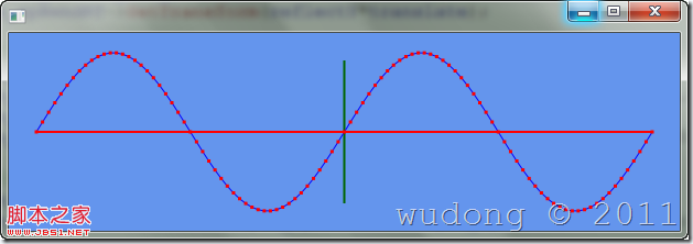
下面是一个使用此函数绘制正弦函数的Sample,曲线的红点是曲线的控制点:
代码如下:
#pragma once
#include "stdafx.h"
#include <Direct2DHelper.h>
using D2D1::Point2F;
using D2D1::SizeU;
using D2D1::ColorF;
using D2D1::Matrix3x2F;
using D2D1::BezierSegment;
using D2D1::RectF;
#include <vector>
using std::vector;
#include <algorithm>
#include <boost/math/distributions/normal.hpp>
class CMainWindow :
public CWindowImpl<CMainWindow,CWindow,CSimpleWinTraits>
{
public:
BEGIN_MSG_MAP(CMainWindow)
MSG_WM_PAINT(OnPaint)
MSG_WM_ERASEBKGND(OnEraseBkgnd)
MSG_WM_SIZE(OnSize)
MSG_WM_CREATE(OnCreate)
MSG_WM_DESTROY(OnDestroy)
END_MSG_MAP()
int OnCreate(LPCREATESTRUCT /*lpCreateStruct*/)
{
CreateDeviceIndependentResource();
CreateDeviceResource();
CreateCurve();
return 0;
}
void OnDestroy()
{
PostQuitMessage(0);
}
void OnPaint(CDCHandle)
{
CPaintDC dc(m_hWnd);
Render();
}
BOOL OnEraseBkgnd(CDCHandle dc)
{
return TRUE; // we have erased the background
}
void OnSize(UINT /*nType*/, CSize size)
{
if (m_spHwndRT)
{
m_spHwndRT->Resize(SizeU(size.cx,size.cy));
CreateCurve();
}
}
private:
void Render()
{
if (!m_spHwndRT)
CreateDeviceResource();
m_spHwndRT->BeginDraw();
m_spHwndRT->Clear(ColorF(ColorF::CornflowerBlue));
m_spHwndRT->SetTransform(Matrix3x2F::Identity());
D2D1_SIZE_F size = m_spHwndRT->GetSize();
FLOAT width = size.width-50, height = size.height-50;
D2D1_MATRIX_3X2_F reflectY = Direct2DHelper::ReflectYMatrix();
D2D1_MATRIX_3X2_F translate = Matrix3x2F::Translation(size.width/2.0f,size.height/2.0f);
m_spHwndRT->SetTransform(reflectY*translate);
// draw coordinate axis
m_spSolidBrush->SetColor(ColorF(ColorF::Red));
m_spHwndRT->DrawLine(Point2F(-width*0.5f,0),Point2F(width*0.5f,0),m_spSolidBrush,2.0f);
m_spSolidBrush->SetColor(ColorF(ColorF::DarkGreen));
m_spHwndRT->DrawLine(Point2F(0,-height*0.5f),Point2F(0,height*0.5f),m_spSolidBrush,2.0f);
// draw curve
m_spSolidBrush->SetColor(ColorF(ColorF::Blue));
m_spHwndRT->DrawGeometry(m_spPathGeometry,m_spSolidBrush,1.0f);
// draw point marks
m_spSolidBrush->SetColor(ColorF(ColorF::Red));
for (auto p=m_Points.cbegin();p!=m_Points.cend();p++)
{
Direct2DHelper::DrawRectPoint(m_spHwndRT,m_spSolidBrush,(*p),5.0f);
}
HRESULT hr = m_spHwndRT->EndDraw();
if (hr == D2DERR_RECREATE_TARGET)
DiscardDeviceResource();
}
void CreateDeviceIndependentResource()
{
Direct2DHelper::CreateD2D1Factory(&m_spD2dFactory);
}
void CreateDeviceResource()
{
CRect rc;
GetClientRect(&rc);
CHECK_PTR(m_spD2dFactory);
IFR(m_spD2dFactory->CreateHwndRenderTarget(
D2D1::RenderTargetProperties(),
D2D1::HwndRenderTargetProperties(m_hWnd,SizeU(rc.Width(),rc.Height())),
&m_spHwndRT));
IFR(m_spHwndRT->CreateSolidColorBrush(ColorF(ColorF::Red),&m_spSolidBrush));
}
void DiscardDeviceResource()
{
m_spSolidBrush.Release();
m_spHwndRT.Release();
}
void CreateCurve()
{
if (!m_spHwndRT)
return;
if (m_spPathGeometry)
{
m_spPathGeometry.Release();
m_Points.clear();
}
const int ptCount = 100;
D2D1_SIZE_F size = m_spHwndRT->GetSize();
FLOAT width = size.width-50.0f, height = size.height*0.4f;
#define SIN_CURVE
#ifdef SIN_CURVE // create sin curve
FLOAT factor = static_cast<FLOAT>(4.0f*M_PI/width);
FLOAT x = -width*0.5f, y = 0, dx = width/ptCount;
for (int i=0;i<ptCount+1;i++)
{
y = height*sin(factor*x);
m_Points.push_back(Point2F(x,y));
x += dx;
}
#else // create normal distribute curve
FLOAT factor = 10.0f/width;
FLOAT x = -width*0.5f, y = 0, dx = width/ptCount;
boost::math::normal nd;
for (int i=0;i<ptCount+1;i++)
{
y = height*static_cast<FLOAT>(boost::math::pdf(nd,factor*x));
m_Points.push_back(Point2F(x,y));
x += dx;
}
#endif // SIN_CURVE
// create Bezier spline
Direct2DHelper::CreateBezierSpline(m_spD2dFactory,m_Points,&m_spPathGeometry);
CHECK_PTR(m_spPathGeometry);
}
private:
CComPtr<ID2D1Factory> m_spD2dFactory;
CComPtr<ID2D1HwndRenderTarget> m_spHwndRT;
CComPtr<ID2D1SolidColorBrush> m_spSolidBrush;
CComPtr<ID2D1PathGeometry> m_spPathGeometry;
vector<D2D1_POINT_2F> m_Points;
};
相关推荐
-

解析在Direct2D中画Bezier曲线的实现方法
Direct2D通过ID2D1RenderTarget接口支持基本图元(直线,矩形,圆角矩形,椭圆等)的绘制,然而,此接口并未提供对曲线绘制的直接支持.因此,想要使用Direct2D绘制一段通过指定点的曲线,比如Bezier曲线,必须借助于DrawGeometry()方法间接实现.需要通过一定的算法,将指定点转换为定义Path的控制点.幸运的是,codproject上已经有人做了这项工作,给出了相应的转换算法,并给出了C#版的实现:Draw a Smooth Curve through a Se
-
OpenGL画bezier曲线
Bezier Curve算法是根据参数曲线方程来得到光滑曲线的一种算法,曲线方程的参数由控制点决定. 其本质是由调和函数根据控制点插值而成,其参数方程如下: 其中Pi(i=0,1,-,n)为控制点的向量, Bi,n(t)为伯恩斯坦Bernstein基函数,其多项式表示为: 线性Bezier Curve由两个控制点决定: 二次Bezier Curve由三个控制点决定: 三次Bezier Curve由四个控制点决定: 如下图,t = AE:AB = BF:BC = CG:CD = EH:EF = F
-
易语言在画板中画指定样式饼形的方法
画饼方法 英文命令:pie 操作系统支持:Windows 所属对象:画板 语法: 无返回值 画板.画饼 (椭圆左上角横坐标,椭圆左上角纵坐标,椭圆右下角横坐标,椭圆右下角纵坐标,弧线起始点横坐标,弧线起始点纵坐标,弧线终止点横坐标,弧线终止点纵坐标) 例程 说明 通过"画饼"命令在画板中画指定样式的饼. 运行结果: 总结 以上就是这篇文章的全部内容了,希望本文的内容对大家的学习或者工作具有一定的参考学习价值,谢谢大家对我们的支持.如果你想了解更多相关内容请查看下面相关链接
-
解析在PHP中使用全局变量的几种方法
简介即使开发一个新的大型PHP程序,你也不可避免的要使用到全局数据,因为有些数据是需要用到你的代码的不同部分的.一些常见的全局数据有:程序设定类.数据库连接类.用户资料等等.有很多方法能够使这些数据成为全局数据,其中最常用的就是使用"global"关键字申明,稍后在文章中我们会具体的讲解到.使用"global"关键字来申明全局数据的唯一缺点就是它事实上是一种非常差的编程方式,而且经常在其后导致程序中出现更大的问题,因为全局数据把你代码中原本单独的代码段都联系在一起了
-
Android中贝塞尔曲线的绘制方法示例代码
贝塞尔曲线,很多人可能不太了解,什么叫做贝塞尔曲线呢?这里先做一下简单介绍:贝塞尔曲线也可以叫做贝济埃曲线或者贝兹曲线,它由线段与节点组成,节点是可拖动的支点,线段像可伸缩的皮筋.一般的矢量图形软件常利用贝塞尔曲线来精确画出曲线. 上面的介绍中,"线段像可伸缩的皮筋"这句话非常关键,但也特别好理解.至于贝塞尔曲线的详细内容大家可以查阅相关资料. Android提供的贝塞尔曲线绘制接口 在Android开发中,要实现贝塞尔曲线其实还是很简单的,因为Android已经给我们提
-
OpenGL实现Bezier曲线的方法示例
Bezier曲线的形状是通过一组多边折线(特征多边形)的各顶点唯一地定义出来的.在这组顶点中: (1)只有第一个顶点和最后一个顶点在曲线上: (2)其余的顶点则用于定义曲线的导数.阶次和形状: (3)第一条边和最后一条边则表示了曲线在两端点处的切线方向. // BezierCurve.cpp : 定义控制台应用程序的入口点. // #include "stdafx.h"</div></div></li><li><div class=
-
OpenGL绘制Bezier曲线的方法
本文实例为大家分享了OpenGL绘制Bezier曲线的具体代码,供大家参考,具体内容如下 项目要求: – 使用鼠标在屏幕中任意设置控制点,并生成曲线 – 使用鼠标和键盘的交互操作实现对曲线的修改. 项目总体介绍 本项目利用Bezier曲线生成算法生成可由用户自定义的曲线.可实现核心功能如下: 1.用户用鼠标左击屏幕任意处产生记录点. 2.鼠标右击屏幕任意处由先前的任意个数记录点和其先后关系生成Bezier曲线. 另有辅助输入功能: 1.按键盘'C'键可清除所有记录点. 2.按键盘'R'键可清除上
-
OpenGL绘制三次Bezier曲线
本文实例为大家分享了OpenGL绘制三次Bezier曲线的具体代码,供大家参考,具体内容如下 计算公式: 运行结果: 代码如下: #include<gl/glut.h> #include<math.h> #include<windows.h> #include<vector> #include<algorithm> using namespace std; struct Point { int x, y; Point(){}; Point(int
-
IOS 开发中画扇形图实例详解
IOS 开发中画扇形图实例详解 昨天在做项目中,遇到一个需要显示扇形图的功能,网上搜了一下,发现code4app里面也没有找到我想要的那种类似的效果,没办法了,只能自己学习一下如何画了. 首先我们需要了解一个uiview的方法 -(void)drawRect:(CGRect)rect 我们知道了这个方法,就可以在自定义UIView的子类的- (void)drawRect:(CGRect)rect里面绘图了,关于drawrect的调用周期,网上也是一找一大堆,等下我会整理一下,转载一篇供你们参考.
-
基于Protobuf动态解析在Java中的应用 包含例子程序
最近在做ProtoBuf相关的项目,其中用到了动态解析,网上看了下相关资料和博文都比较少,自己来写一个记录一下学习过程. Protocol Buffers是结构化数据格式标准,提供序列化和反序列方法,用于存储和交换.语言中立,平台无关.可扩展.目前官方提供了C++.Java.Python API,也有其他语言的开源api(比如php).可通过 .proto文件生成对应语言的类代码 如果已知protobuf内容对应的是哪个类对象,则可以直接使用反序列化方法搞定(Xxx.parseFrom(inpu